High Availability Architecture
This page outlines the different server architecture components that are needed to build out a scalable, high-availability LiveSwitch infrastructure.
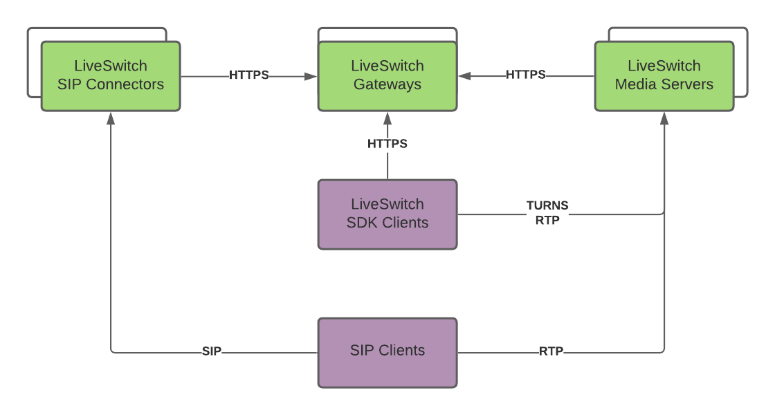
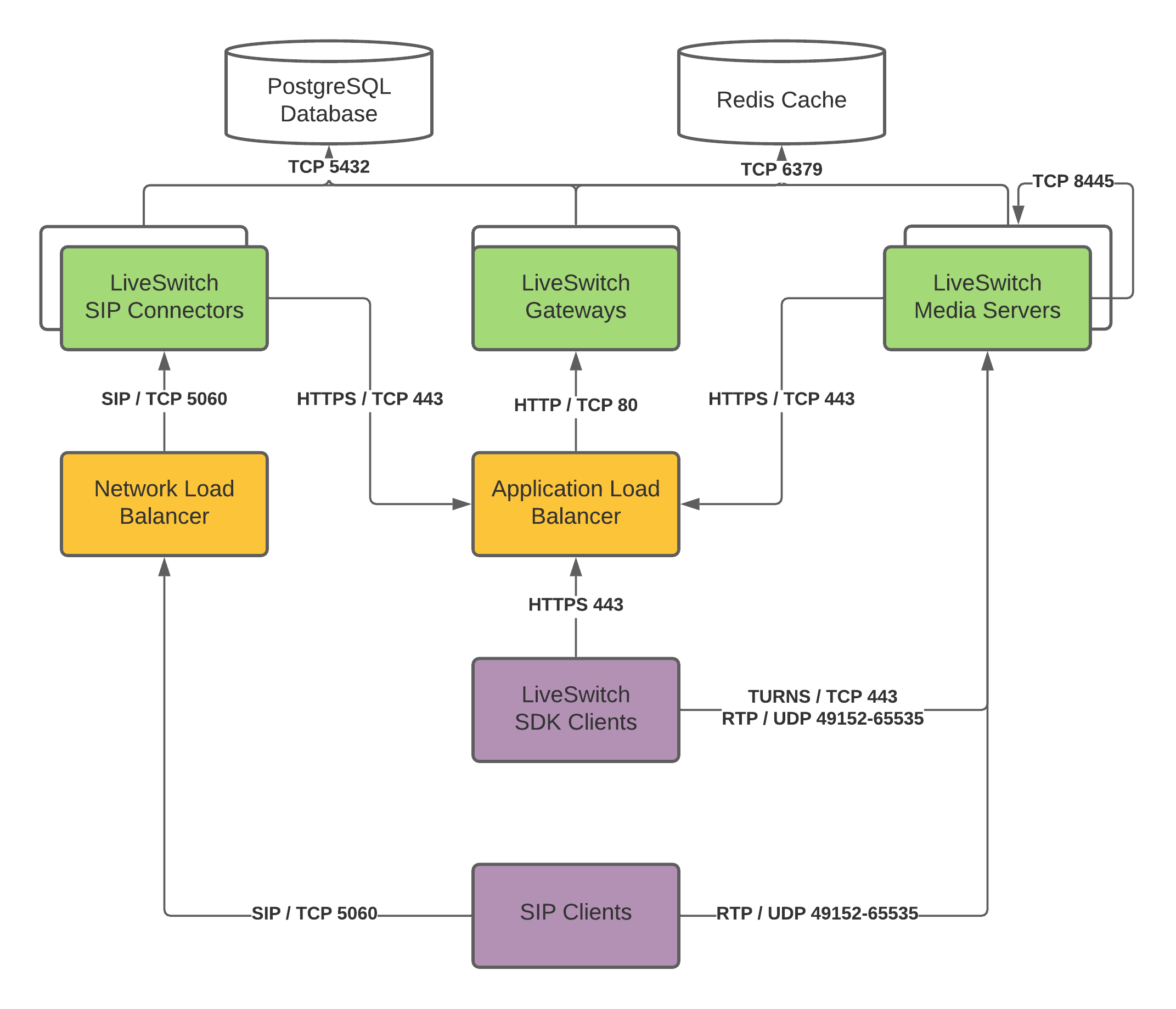
At a basic level, you need multiple Gateways and Media Servers deployed on your infrastructure to ensure high availability. Below is the high-level diagram of the architecture:
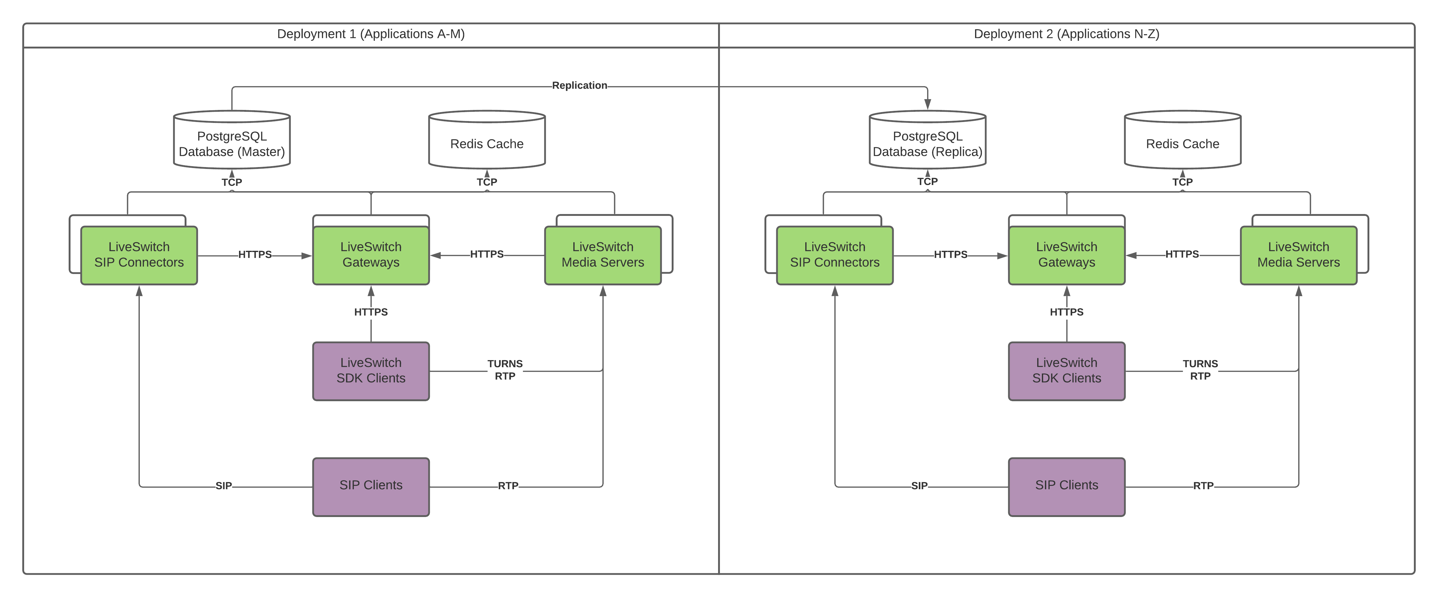
You can organize the infrastructure into multiple regions, additional provider specific settings, and so on. Below is the typical infrastructure for high availability and geographic distribution using the cloud provider of your choice:
User Interface Components
Custom Solution Client
Each custom solution requires one or more custom client app components that integrate with the LiveSwitch SDK. LiveSwitch provides client SDKs for all modern platforms, with libraries written in C#, JavaScript, Java, and Objective-C. We support Android, iOS, macOS, almost any flavor of .NET, Windows 11, and a few other minor platforms.
For standalone apps, like a mobile app or desktop app built in .NET, you should configure them to target the LiveSwitch Server components.
For hosted apps in the cloud, like a web app, the custom client app should follow best practices for highly scalable and highly available systems. The specifics of this setup vary depending on the different custom components that make up the client's custom app. It's likely that a combination of multiple servers in availability zones with load balancers is required to ensure that the custom solution is highly available.
LiveSwitch Configuration Console
The LiveSwitch Configuration Console is available on the LiveSwitch Gateway. To help ensure that access to this console is restricted to administrative access, we recommend that the cluster of Gateway servers are behind a load balancer. Only IP addresses that are part of an allow list should be allowed through this load balancer.
LiveSwitch Server Components
LiveSwitch Gateways
To connect the client app to the LiveSwitch Media Servers, a signaling process determines how these two entities communicate through WebRTC. For a high-availability architecture, there must be at least two Gateways installed in separate availability zones and in the same region. This is the LiveSwitch Gateway cluster. There may be additional Gateway servers that are added to the cluster as the application scales to handle more load.
Gateway Admin Load Balancer
The Gateway Admin Load Balancer is configured with a DNS name and certificate for the admin console. This load balancer accepts HTTPS traffic from an allow list of IP addresses to help ensure security of the LiveSwitch Admin Console that resides within the Gateway. This load balancer terminates the HTTPS traffic (over port 443) at the load balancer and then directs the requests through HTTP to port 9090 on one of the LiveSwitch Gateway servers in the cluster.
Gateway Client Load Balancer
The Gateway Client Load Balancer is configured with a DNS name and certificate for the client signaling of the LiveSwitch configuration. When the custom client app begins the signaling process with the Media Server, it signals requests to the Gateway Client Load Balancer. This load balancer terminates the HTTPS traffic (over port 443) and then directs the signaling requests through HTTP to port 8080 on one of the LiveSwitch Gateway servers in the cluster.
Redis Instances
LiveSwitch Gateways use a Redis backend to ensure that ephemeral client information is available to all Gateway servers. There should be multiple Redis instances, over more than one availability zone, to ensure reliability. Redis is used in a single server mode with failover.
Postgres Database
A LiveSwitch implementation’s settings and configurations are stored in a Postgres database. These values are written by the Gateway as changes are made to the configuration in the LiveSwitch Console.
Read/Write Nodes
The Postgres implementation should have a multi-availability zone configuration for read/write. This LiveSwitch Gateway communicates over port 5432 to the read/write node of the Postgres database cluster.
Read-Only Nodes
For LiveSwitch Media Servers to access configuration settings efficiently, add read-only nodes to the Postgres database for the Media Server to use.
LiveSwitch Media Servers
The LiveSwitch Media servers forward and mix audio and video streams used in the WebRTC conferences. The proximity of these servers to the users involved in the conference are important to help reduce latency, so deploying Media Servers into multiple regions in addition to multiple availability zones is wise.
Private VPN
To reduce latency, create a private VPN connection that the LiveSwitch Media Servers can use to communicate with each other, the Media Server Signaling Load Balancer, and the Postgres and Redis instances.
Media Server Signaling Load Balancer
Media Servers and client apps need to participate in the signaling process through the Gateway server. Rather than use the Gateway Client Load Balancer, a separate Load Balancer is used for the Media Server signaling to the Gateway. This load balancer accepts HTTP traffic over port 8080 instead of requiring HTTPS traffic because it only accepts traffic from the private VPN connection.
Media Clustering
LiveSwitch Media Servers use a private IP address range to ensure security between different regions.
Firewall (1:1 NAT)
To ensure security for the Media Servers, a firewall is established with a 1:1 NAT configuration. This firewall only allows media to flow on UDP ports 3478 and 49152-65535 and TCP ports 443 and 3478 which are used with WebRTC.
LiveSwitch Bandwidth Requirements
Typically, but not always, a high-quality video feed on WebRTC uses 2 Mbps. A good-quality video feed can still occur at 1 Mbps. 500 Kbps is sufficient for group calls because individual feeds usually have smaller resolutions.
In addition, LiveSwitch supports simulcast. Simulcast allows the originating source in a group call to send out multiple streams at different bitrates. Receiving participants then select a feed based on their available bandwidth.
LiveSwitch Server can be configured to cap the bandwidth into the server, putting control of the network usage into your hands. The client app maintains full control, up to the caps the server implements, through the use of TargetBitRate APIs. Note that the TargetBitRate is capped at the maximum server threshold, and actual throughput may be lower based on network availability. If you wish to customize this, you can utilize the connection.GetStats() API to read for any lag, loss, and frame rate questions on your end device, and modify the TargetBitRate value accordingly.
Audio feeds are typically around 32 Kbps.
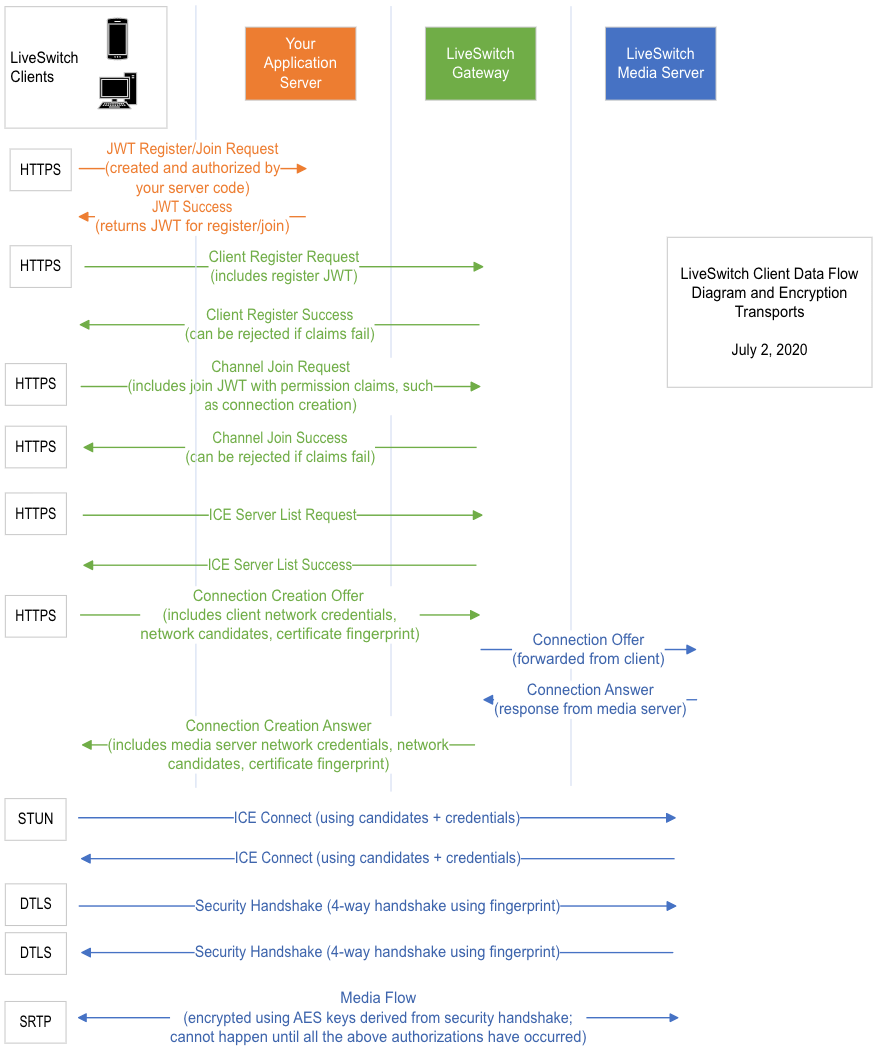
LiveSwitch Client Data Flow Diagram
Understanding how the client registration and connection process works is important to understanding the security of LiveSwitch, as well as the architecture. The process through which a LiveSwitch client can connect to a Gateway and stream media through a Media Server is explained below:


